Announcement

Collapse
No announcement yet.

Team Death - New Heavyweight

Collapse
X
 
  • Filter
  • Time
  • Show
Clear All
new posts

  • #46
    Thank's Dave I'm glad to hear you love our Robot and I'm pleased to say
    shes single .
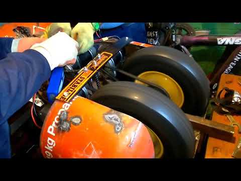
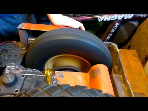
    Euan is right the wheels cant slip sideways as they are very tight between
    the bearing hubs, the wheels dont have bearings themselves, they sit on
    the spindle 22mm thick and are bolted to it and the sprocket is welded to
    the spindle shaft.

    Comment


    • #47
      A delayed blog post this week, as I was preoccupied for a while with MRI scans and the buying of a car, but here we go, better late than never!
      Sunday was a day of progress, and we got a few things done.
      Sometime since the last post, Colin had acquired a winch, a video of its pulling power below,, which will later become the mechanism for closing the jaws. Using a chain going to each jaw, being tied into one, and when the motors engages, the force pulls both jaws shut simultaneously.
      Our main task for the day was fitting this into the machine, which was surprisingly simple, it just took a single piece of metal being fabricated, drilled into it, and a nut welding to one side of it for easy tightening and later removal, then the metal being welded inside and winch pulley being mounted to it. The winch uses its own motor, which needs to still be positioned. The motor uses the same voltage as the main motors, so a seperate power source or system isn't required, but only optional depending on some factors later down the line.
      We also worked out a return system, using some springs so, when the motor has disengaged, the jaws return to their open position near immediately. This system currently needs a little more refining, but the proof of concept was certainly there.
      Part of the jaw opening requires a double sprocket, so the motor can turn it with a little chain, and in turn, turn the other chain leading to the jaws. This is to stop us needed an exceptionally long chain that might be prone to being knocked out of place or off the sprocket, two smaller chains may be more reliable than an exceptionally long one. I'll be going to a local store in Wakefield that sells bearings during the week to acquire this.


      Sundays images,
      1 An image of the actual winch Colin acquired, it was taken off the plank of wood prior to installing into the bot.
      2 A close up of the jaw mechanism, showing the springs used to return the jaws to position when the pulling motor disengages.
      3 The current state of the internals, after the winch system was installed, still to do is fitting the controlling motor, this will be done next week most likely.
      IMG_20170827_122703.jpgIMG_20170827_134439.jpgIMG_20170827_152101.jpg

      There's also two videos;
      Demonstrating the action of the jaws, demonstrated by Colin pulling on the control chains here, they were hard work to pull, so never quite made it to full closure, but it certainly gives you an idea: https://youtu.be/XRN5tnT1Xt8
      The strength of the motor in the winch, we're intending on using this motor, but we're aware we might need something a little more powerful to not only pull the jaws together, but also maintain a good grip on anything caught in the jaws. So the end force may be stronger than this:
      https://youtu.be/RCTM-vTomSg

      Some machines have a death hum, but if those jaws are anything to go by, we have a death rattle!

      Comment


      • #48
        Car boot Bargains and Robot application.
        Captains log engineer scott reporting sorry coulden't resist
        its been a star trek kind of end to the day.
        I visited the car boot as usual before Adam arrived to help with
        the Robot build and once again bargains were to be had.
        First purchase was a caravan stablising bar for £2 then
        a steel plated plywood boogie on castors-instant robot for someone, a 5kg box of nuts and
        bolts for £2 and a stainless steel sieve for 20p.
        At the end of the day I cut up the sieve and used it to cover
        protruding motors and as the sparks flew through the holes
        it just reminded me of star trek special effects.
        DSCN1790.jpgDSCN1791 (2).JPG

        Comment


        • #49
          Following on from Colins post about the car boot, I'll post about how some of it came in to use in todays building session!


          Today was mostly spent getting the double sprocket ready - this will take the motor chain over the sprocket, and in turn pull on the jaw chain. This was deemed a better solution instead of having one rather long chain running most of the length of the insides, splitting it into two seperate ones.
          The first thing we did was to prepare a little mount for the sprocket, so it could turn independently of everything else using the bearings I had acquired over the week (see image 1). This was a fairly simple task, once we had decided on the suitable metal thickness and such to ensure strength over load and no bending possibilities.
          After we'd done, we needed to find a place to mount it to. It became clear last week that we'd need to make a mount ourselves, as the ideal place was floating above everything, and we're not wizards nor above the laws of physics just yet.
          Enter the stabilising towing bar Colin mention on the previous post!
          After sending it on a crash diet course, courtesy of an angle grinder, it was cut down in length to fit neatly on the bottom of the robot. After being bolted in place (see image 2), so it could be rapidly removed so we can get to the internals and replace wheels. We lined up the previously put together sprocket and mount and it all lined up neatly (see image 3)
          Unfortunately, the time ran out before this was put together, Colin may find the time to do it during the week, if not, that'll be the first thing for next sunday!

          DQuWBCI1.jpgsd7EJfRu.jpgW0IiyzoJ.jpg

          Comment


          • #50
            Another Sunday gone, another day doing things.

            Today was a fairly one track day, and we spent it mostly on mounting the motor for the weapon mechanism into the system. This required some extra exhaust brackets, which come in very handy for mounting these sorts of motors. We then also needed to source a strip of metal to mount the brackets to, and then the entire thing was welded into the robot after a bit of headscratching, as the initial mount was hugely out of whack with the position of the previous dual sprocket it needed to link to, we never really figured out for sure exactly how we made that mistake, but we recovered and didn't repeat it, which is the important part!
            Unfortunately, purely by lack of forethought on my part, we didn't photograph the actual end unit comprised of the brackets and mounts to demonstrate that. So you'll have to use imagination for that bit. We ended up having to mount one of the brackets on the outside of the bot, as otherwise the two brackets would be within a couple of inches of each other, and not all that supporting overall, not to worry though, as that, plus the poking out motor, will be covered by an extra layer or two of cover and armor by the end.

            However, we did at the end take some images of the current situation in its entirity.
            The first image shows the entire assembled unit welded to the bot, this takes up the gap at the top of the main circular unit, and holds the motor (visible to the right of the image, sticking out) in place very well.
            Second image shows the entire under side of the bot as it is now. A huge array of chain going everywhere, imagine the noises that'll make when everything is going simultaneously! Hopefully keeps with the industrial look of everything!


            u19ZOLlU.jpgtkrnaaXH.jpg

            Comment


            • #51
              The favoured day of the week (Sunday) for Robot building went reasonably well
              -you never seem to get all you want to do done but progress was made never the less.
              Adam and I were joined by Adams friend Niall and we seemed to work well together
              with each having a knowledge in certain areas.

              We mainly worked on the jaws system again, including the winch,chains,and sprocket
              system.
              First we removed the winch as the webbing was far too long for our purposes so we
              cut it down to a reasonable length, secondly we cut out a hole in the robot frame to
              insert an encapulated nut under where the winch sits and bolted it back in place.
              After shortening the jaws pulling chains and linking them together
              with a split link we turned our attention to the double sprocket that was held onto
              the snakemaster stablising bar by mole grips.
              Niall suggested that bolts were the prefered method for holding it it place so we
              set about drilling holes in the snakemaster metal strip-this turned out to be
              pretty tough going but after sharpening the drill bits between drilling the
              breakthrough was made and the sprocket bracket is now bolted in place.

              During the week I had fitted a sprocket to a matching drive motor we had
              bought and fitted this motor and chain into position.


              DSCN1821.jpgDSCN1823.jpgDSCN1822.jpg
              Last edited by team death; 17 September 2017, 20:26. Reason: adding picture

              Comment


              • #52
                Hi all, I just wanted to introduce myself as the newest member of the team. I'm mostly experienced in the electrical side of things so I'll be taking that on as a main responsibility.
                We made good progress this week on getting the weapon functioning better. We cut the teeth for the jaws, and have been working on the spring return system for them. Our new springs are from a chest expander, Champion brand and everything!

                IMG-20170925-WA0002.jpg

                Here's a close up of the teeth we cut from a template, they seem to be very sturdy and we are confident they'll take a good bit of abuse without breaking.

                IMAG0404.jpg

                In other news, with last week's progress made to the chain drive for the weapon, the current weight is now at 82kg. Took a fair bit of effort to get it up on the scales!

                IMG-20170925-WA0000.jpg

                And lastly, with a little help from one of our new springs, we got the weapon to close and return under it's own power! Still a few bits to smooth out to get reliable operation but it's great progress.

                Comment


                • #53
                  This is awesome. Like next level awesome.

                  Comment


                  • #54
                    The sound of all the chains and motors going simultaneously will hopefully rival the famed death hum in the intimidating factor! Certainly makes a racket!

                    Comment


                    • #55
                      Apologies for the late update!
                      Since last week, improvements have been made to the weapon chain system, each side's chain now has a guide to allow them to move much more freely and reduce stress on the chains and winch system.

                      IMAG0432.jpg

                      Good progress was made on the drive this week, with both sides' axles being removed in order to have flats ground into them to prevent the wheels from slipping on their axles. This proved very effective, once tightened we couldn't get them to budge.

                      IMAG0429.jpg

                      We also made adjustments to the general fit of the wheels, with some generous grinding and re-positioning in order to reduce any contact between the wheels and chassis. This still needs a little fine tuning, which will include photos in next week's update, but for now things were improved to the point where we were able to run both drive motors, currently on half voltage for demonstration purposes.


                      Thanks for reading this update, and stay tuned for next week's post!

                      Comment


                      • #56
                        Reaching The Finishing Line.
                        Having built Numerous Robots in the past you tend to know when your'e
                        reaching the finishing line of the build process.
                        Todays build was aimed mainly at the electronic aspects and Niall or Adam will
                        cover that topic, but there was some light fabricating work to be done first.
                        The speed controller needed a housing, so I cut a oblong slot out of the
                        top of the Robot just slightly larger than the controller and then searched
                        the workshop for a suitable metal housing.
                        Previously we had used metal from a Bath mate (lifting sling for the bath) and
                        it was to come in handy once again, containing a box shaped piece of metal
                        that was the perfect fit for the slot I had just cut to take the speed controller.

                        Other light fabrication included bolting on a steering box adjuster to cover
                        a hole in the bodywork and welding on a inner tail plate at the back of the Robot.
                        Image 1=Bath Mate and inner workings
                        Image 2=Steering box Adjuster
                        Image 3=inner tail plate
                        DSCN1856.jpgDSCN1860.jpgDSCN1858.jpg

                        Comment


                        • #57
                          Further to Colin's post, I have a few more photos to add from the new speed controller housing. first showing it's new home within the chassis, and second showing the hinge we installed for easy access to the ESC.

                          OAjF5NS.jpg

                          SsjdJiO.jpg

                          And as for the electrical side, a lot of progress was made towards getting all the relevant connections in place. Our main connectors to and from the ESC are all being taken care of with the pictures EC5 connectors. These were installed by means of a windproof lighter repurposed as a mini torch.

                          O7AsXqfb.jpg

                          It was then time to connect our batteries in parallel using a 5.5mm bullet to EC5 cable I had made during the week. The lead makes one positive and negative connection to the battery pack, providing a nominal 28 volts. Here's a photo of the arrangement for full voltage testing of the drive motors.

                          ibfm0UGl.jpg

                          And here's a little video of the left wheel drive motor on around 29v from the two series batteries. Tons of power there!


                          As always, thanks for reading this update and stay tuned for next time!
                          Attached Files
                          Last edited by Captain Foxbunny; 8 October 2017, 19:52.

                          Comment


                          • #58
                            Most of our work this week has been focused on getting the electrical side sorted out. First on the agenda was getting both drive motors fused, using 80A midi fuses, pictures still pending while we work on cable management. But the main thing was getting a fuse to protect the ESC and batteries. A little work with a bench vice was enough to crimp the huge terminals on this fuse holder. We have a choice of 200 and 250A fuses depending on our final load.

                            IMAG0464.jpg

                            And once closed up, it becomes the biggest in-line fuse holder I've ever used! As you can see the fuse rating is still identifiable even with it closed.

                            IMAG0465.jpg

                            Also on the electrical side, I started work on linking our receiver and ESC together. For our left and right drive motors, I have colour coded a 3-cable bundle for each channel, they aren't the prettiest as it is proving difficult to find the connectors I need, but I'm more than happy how well they came out!

                            IMAG0471.jpg

                            Finally this week, following up to the mounting box made for our ESC in last week's post, a piece of thick lexan was made to protect the ESC box. This bolts in place using the pre-existing tapped holes in the metal used to make the box.

                            IMAG0469.jpg

                            Stay tuned for next weeks post and thanks for reading!

                            Comment


                            • #59
                              Mixed Fortunes this weekend on the Robot building front
                              I had ordered some parts online to make the removable link and
                              typically ebay sellers with high feeback scores send poor quality
                              goods or in this case the wrong item so I ended up buying parts
                              locally to make some progress.
                              It can be a bit of a headache when it comes to where you
                              place the removable link, you need to make it easily accessable but
                              at the same time protected against axes and spikes and spinners.
                              So after a bit of head scratching I decided to place it in the wheel arch
                              and it worked well-protected and still easily removed even if blindfolded.
                              The previous week, Niall described the housing for the Speed controller
                              and I decided to place a secondary housing next to it to house the RC battery
                              pack and reciever, this has a piece of polycarbonate to protect it and a dome
                              metal cover (fire extinguiser bottom) covers both housings.
                              I confident this multi layered system will protect the delicate electronics from
                              the likes of Thors axe.
                              Adam was struck down with a bug at short notice and wasn't
                              able to come but Niall came through to help out on Sunday.
                              I have allways used my own basic relays in previous robots and
                              with a bit of luck we hope to use a speed controller in a team death
                              robot for the first time, i'm anxious to see this work even in static
                              mode with the wheels off the ground but I'm also aware that the ESC
                              is the most expensive bit of kit we have bought for the Robot and
                              great care is needed installing it.
                              DSCN1873.jpgDSCN1874.jpgDSCN1878.jpgDSCN1872.jpgDSCN1879.jpg
                              Picture 1 removable link housing in position
                              picture 2 tried and tested removable link type
                              picture 4 housing for reciever and ESC
                              Picture 5 cover made from fire extinguiser
                              Picture 3 top view of robot
                              For Some reason the pictures didn't appear last week so here
                              they are-more to report tomorrow
                              Last edited by team death; 28 October 2017, 17:19. Reason: pictures didnt display before

                              Comment


                              • #60
                                Another Sunday passed!
                                For the first time in a while, I'll be delivering the blog update this time around! We were down a man again, as though I recovered from my illness, Niall was up in Scotland, but should be back for next week!

                                Today was another day of misses, with a recovery towards the end.
                                As soon as I met up with Colin, we took a trip to Maplin, and got some ceramic 1 ohm resistors of varying wattages. These were to be used to try nulling an issue with getting things up and running, when the battery was connected there was a huge spark. The plan is to have a resistor make the first connection, and ease the flow of energy in before the main connection is made, similar to how a British style plug works, the earth pin is slightly longer so it always makes contact first, where the longer pin would be the resistor pin here.


                                After getting back to the workshop, we had a go at getting this going, however instantly ran into issues. Unfortunately try as we might, our new Ragebridge ESC wasn't powering up, and after slowly removing stuff from the circuit trying to problem solve the faulty component, we came to the conclusion the actual ESC seems to be not enjoying the situation. We will hopefully have an update on this situation and a way to resolve it by next Sunday.


                                Unfortunately, all this took around 2 hours, but after realising we were not going to make progress there, we moved onto some more fabrication. First on this order was to make a set of battery holders on each side of the bot, they'll conveniently hold the batteries in place, but also add additional protection, as LiPos are not too fond of being pierced with hammers and axes, and competitors have lots of those! They've been put on hinges welded to the main body, so they can be quickly moved up and down in and out of place.
                                This didn't take too long, so we had time to do some work on the castors for extra handling, we cut a few pieces which will soon hold the castors in place. They'll be back with some springs, so they're always on the floor. Final order of the day was to drill a hole, for the castor to fit through. This last part will be repeated later on for other castors.


                                We currently think all major fabrication should be done within the next 2 or 3 weekends.


                                A few images for today;
                                The three ceramic resistors, all slightly different so we can play with what works better for what we need.
                                The rather large mess of electrics whilst we were trying to get the ESC to power up.
                                A close up of one of the battery holsters
                                Locked and loaded, batteries in place!
                                Some previous fabrication work done by Colin, and a little of what was done today, and will be continued on soon, for the castors.


                                KK2ZOH8e.jpg7A9L5Jie.jpgPIbUN6D5.jpgPRm9ksCr.jpg9WFsj12h.jpg

                                Comment

                                Working...
                                X