 Tweet
Tweet
As above! Needing some inspiration, if anyone would be so kind as to stick up some pictures of their grand designs!
-
-
I'm quite liking this "Show us your" series. -
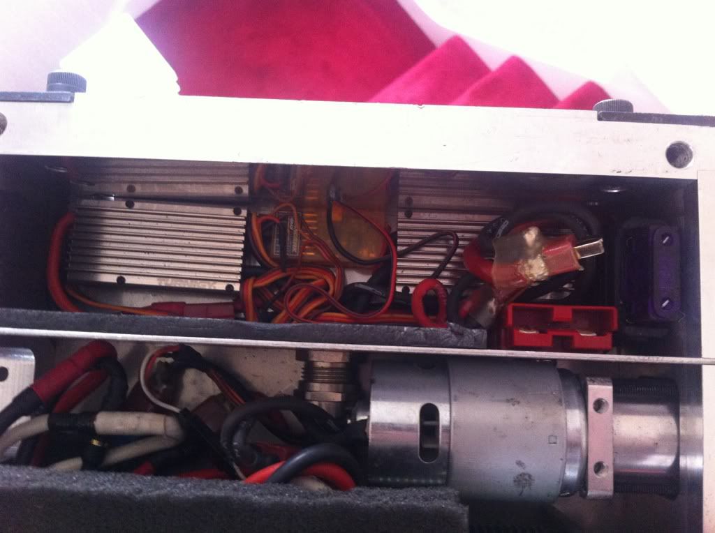
foam below, and on sides, then some on the armour that goes over the top, holding it snugly in place... then theres the fuse and link next to it in the same compartment...all cables go out below the lipo through a gland.. incase a fire should start it prevents it getting to the other side of the robot.Comment
-
ive used some aluminium U section then riveted a piece of flat bar in either end and used foam take to cushion the battery and i have a aluminium top plate that uses Velcro to keep it in placeComment
-
This is awesome! How do you come up with these ideas lol!Comment
-
Nice design Dave, what do you use to distribute the power to the 2 drive ESCs and the weapon ESC. I've always used Terminal blocks, but A) they undo over time and B) fitting 3 fat cables in each side is getting tricky.Comment
-
If it's any help, in Drumroll I have this:
dr2_build (128).jpg
If you crimp ring connectors on to each wire, you can connect positive to one bolt and negative to the other. From there, you just bolt on each component that needs power (drive escs, weapon escs, LED etc). You just need to take care that there is no possibility of something shorting out the bolts and wrecking your battery and/or robot.
Not sure how Dave does it though I'm keen to see; was looking at the pic of 720 above thinking 'man, that really is a compact robot, no space for anything else'
Then I noticed that was without a drive motor!Comment
-
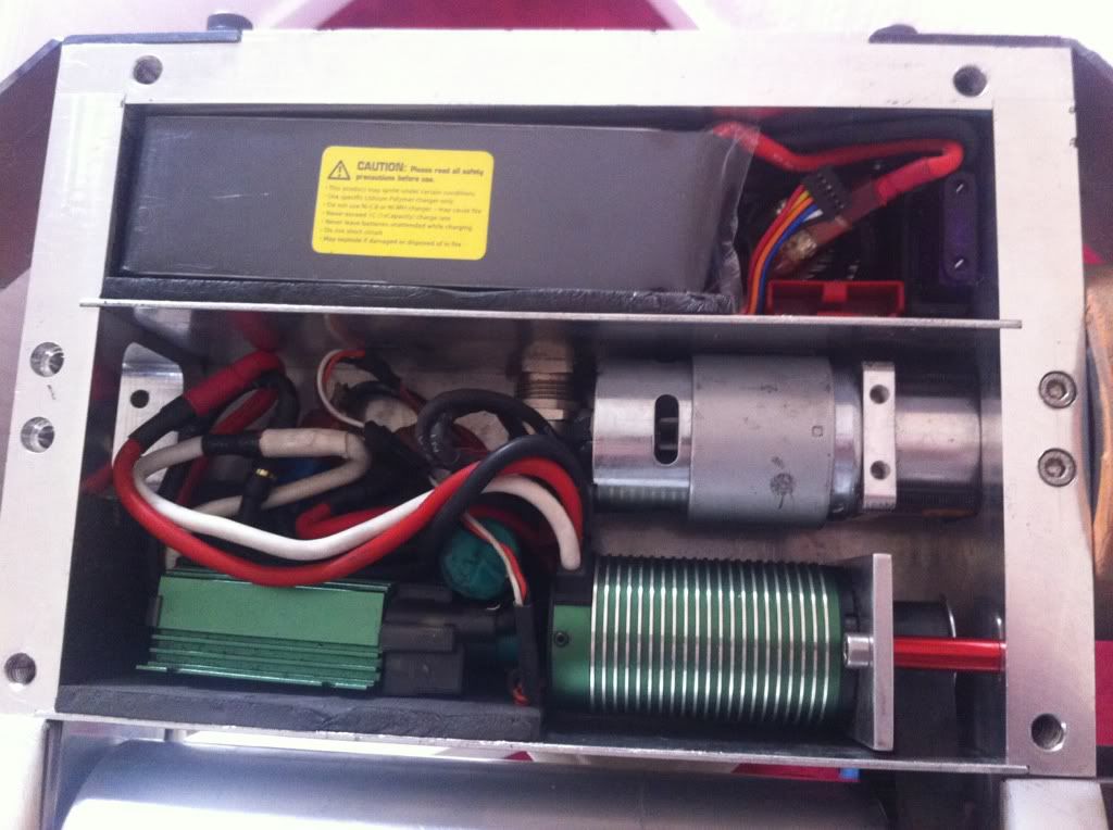
Each component is on its own deans connector, that way there’s no messing about if a component needs to be swapped out, then there’s a main loom to the robot.. basically it’s all on deans and every dean apart from the last one has 2 wires soldered to each tab… for example if you need to get power to two botbitz escs each on its own deans connector.. I would have a positive supply to the first connector, then of the same tab, another wire going out to the second deans connector for the second esc…. So pretty much all the components are daisy chained up. It’s the way I’ve always wired things up, and I’ve never had a problem.
Apart from the main supply to the brushless esc which runs its own supply direct from the link.
And yeah its pretty tight... Hopefully ill have a flip switch for next year... dont know where im going to put it yet..this is the view of whats under the foam below the lipo lol;
Comment
-
I've used these (well similar with a cover)
http://www.ebay.co.uk/itm/Terminal-B...item53f6408ee4Comment
-
@Jamie, I had noticed before that you use ring connectors and bolts. Looks like a sturdy system but is begging for a short!
@Dave, I think I follow..... Either way you've given me a good idea of how I'm going to do it in my next bot!
Where did you get your fuse holder? I couldn't find one that was mountable, or not massive for being waterproof.
Is there a reason why people don't use Fuses as removable links?Comment
-
http://www.ebay.co.uk/itm/In-Line-Ma...ht_2337wt_1328 is my fuse holder.. i just choped of the top cap, its a bit big to be honest, but i had one kicking around at the time so i used it.
And some people do use a fuse for a link... fuse's can pop though if they get a sudden in rush of current- which is what a link gets everytime you plug it in... so i wouldnt suggest it.
edit - the fuse isnt mounted to anything, theres a short cable between the fuse and link, and then its just wedged in, doesnt need a mount because it has no where to go!Last edited by Mouldy; 24 April 2013, 13:41.Comment
-
This is awesome! Thanku to all!Comment

Comment