 Tweet
Tweet
Most robots, or at least my two(both running sabretooth ESCs), needed adjusting. The ESC usually does most of it for you, but are you sure switch 5 is up? Because that controls the auto calibrate and my robots have it turned on. If that doesn’t work, try nudging the nubs around the control sticks to trim it. It’s just a case of trial and error.
-
Last edited by Theo; 8 November 2017, 00:14. -
Dip 5 is down and off. This was as per the instructions in the Haynes Manual.
The recommendations were as follows:
1 - Mixed - ON
2 - Exponential - ON
3 - Lithium - ON (recognises 4 cells)
4 - Ramping - OFF
5 - Auto Calibrate - OFF
6 - Timeout - OFF
That's how I set them - but will definitly try your adviceComment
-
If that doesn’t work, adjusting the trim seems like the only option left but that will probably sort it. Hope it goes well anyhow!Comment
-
Thanks Theo that seemed to work. However I have trouble getting axles in my wheels. The internal diameter of the bore is 13mm the max bit size in my drill motors is 10mm which I only discovered this after buying some nice M12 bolts and packing with PTFE tape to fit them nice and snug. So I am still unable to do a full test.
This picture is of the M12 bolts
IMG_20171108_185038.jpg
So as I said the aim of the project was to get a rolling chassis, so I am not quite there but so, so very close. I cut a base plate from some hardboard used some jubilee clips to fix the motors, picked up a castor wheel from B&Q for a couple of quid. It moves! It's a bit rough and ready But as already mentioned due to to having to fudge the axles not very well. If I apply any power quickly they just spin. Need to fix this. Perhaps I can find a reducer,I had no luck in B&Q or Screwfix.
IMG_20171108_210448.jpgComment
-
This is the same problem I have at the moment; the wheel bore being that ever so bit big. Tape has worked ok for me in testing, but won’t stand a chance in combat, plus the motors also just spin if I suddenly apply power. I’d suggest Banebots wheels but they only do awkward American measurements to my knowledge. Smaller wheels might work better if you can sacrifice the ground clearance, around 100mm would work better and reduce the motor spinning freely. If it’s just for testing, though, this setup should do for now but I’d advise you to fully modify them (locking down the clutch mechanism) for combat but that’s for another day.Last edited by Theo; 9 November 2017, 00:11.Comment
-
Could you not flatten off a side of the shaft (or cut a keyway in) and then get a wheel hub that uses a grub screw to hold the hub onto the shaft (like this for example?)Comment
-
Thanks for the advice. In my case the large washers and PTFE really held them solid. Turning up the torque on the blots would be very solid. I could further strengthen by drill 4 small holes through the washer and hub and bolting them in. Even some small screws, fixing the washer to the hub would work for this class I think. As you see they are chunky hubs. Plan for now is lighter wheels with smaller bore. But if I find a solution I may put them back on. This is only a 'test bed' but they looked so tough and chunky a real shame.Originally posted by Theo View Post
IMG_20171108_185022.jpgComment
-
Ah I think I see. I can imagine fixing the wheels securely is a major task for many robots. Certainly using drill chucks is easier at this stage. I was looking at the drill motor mounts on the forum and if I did use those I would need to find another way. For now I hope this next set of wheels have 8mm or 10mm hubs (there seems to be some confusion on the website). Either way some 80-100mm bolts, suitable washers and nuts should give me what I need to let me get it ready to whip around the garden patio.Originally posted by Ocracoke View PostComment
-
Why I chose fairly big wheels - I gave it some thought and I see some advantages:
- A larger wheel makes more contact with a surface than a smaller one
- The rolling circumference is larger, so a higher top speed is achieved for same RPM and more control at low speed
- Larger wheel can flex more shock/energy absorption
- Allows more flexibility in mounting position so in theory with correct design the ride height could be adjusted
In all my designs I intend to use the biggest wheels I can get away with for the above reasons.Last edited by Deathly Hallows; 9 November 2017, 08:50.Comment
-
The converse of using big wheels is that they present a bigger target if mounted outside of the bodywork so you'd need to consider how you'd protect them.
The Honey Badger 2.x uses some RC car wheels from a 1:6 (I think) monster truck which measure some 110mm diameter by 40mm wide wheels, which are secured to the wheel hub by some M5 bolts. They have been thoroughly abused, way more than its intended application but are still in round and in one piece.
As an aside, it stuck me when I first saw your robot, it looks vaguely like a old Battlebots competitor, Das Bot from Season 1.0 (http://battlebots.wikia.com/wiki/Das_Bot).Comment
-
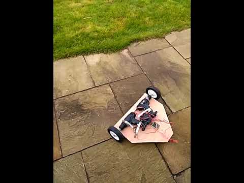
Not raining and I had an idea how to fix the wheels. So this still has temporary axles and is just a test bed. Hell it's quick! I think I got my calculations wrong for my speed estimate. I need to measure them again, I wonder if the diameter was just the hub? With so much weight at back it definitely needs wheelie bars. I need to retain the battery and build a cover or at least roll bars. Then I can play with this and improve my driving skills while I design the my first real robot. I would plan to have inside wheels if possible. Weight could be the issue though, I need to weigh what I have already and see what I have to play with for chassis, armour and weapon.
Note: the sticks have ramping on and I never got more than a few degrees of movement. When I tried I wheelied and flipped. May need to adjust the gearing to slow it down a tad.
Comment
-
I doubt at this stage you'll have an issue with weight- mine weighs at 9.6kg with a similar "rear heavy" setup where I even went and added about 600g of ballast to the rear to keep the rear wheels from breaking traction. The wheelie problem you may find simply goes away when the body and weaponry is added.
Looks good though, keep it up
Comment
-
Very progressive speedy building-I made a similar baseboard a few years
back with the drill layout identical, I was going to make a fleet of four
for pay as you battle events but lost interest.
There's no reason you can't continue with this concept into a fully
working featherweight.
I found that when the drill was reversed the spindle tended to come
loose in the chuck so you could maybe weld it in and the jaws shut and
also the bearings in those drills are designed to take a downward force
not support a laterall weight so you would need to fit a bearing and extend
the spindle at the other side of the wheel.
Some kind of weapon will pevent the front end flying up when you drive.Comment
-
Cheers - thanks for the feedback.
Yes when I ramped up the spin (couldn't help my self a little vistory spin) at about 80% power the wheel flew off. But by then the thing was a blur. That was hand tightened. Now I have used two grips and taken it as tight as it will go. When I convert this to a battle bot I will probably change the connection if I find a good alternative.Comment
Comment