Announcement

Collapse
No announcement yet.

Unnamed FW crusher build diary

Collapse
X
 
  • Filter
  • Time
  • Show
Clear All
new posts

  • #31
    Update time again, and since I still can’t find any previous robots with the name of Pressure Point, I’m going with that.

    As expected it’s the little repetitive jobs that are taking all the time. First up, I have finished attaching the front wedge onto the chassis. To keep things simple, I’m holding it all together with holed and threaded square section, taking the inspiration from Pulsar and the like. This means I have been starting with plain 12mm square 6082 aluminium section, cutting to length, drilling holes in it, threading the holes, drilling matching ones on the pieces to be joined, countersinking them and so on…..And its time consuming, but all part of the fun. After a while, the front wedge was properly attached.

    Next up, the housing at the back for the drive motors. This part is designed to be modular so it’s easy to remove for repairs or to swap/upgrade drive motors at a later date. All made from HDPE, the parts have been cut out by a friend on his CNC. There are 2 of the Argos value 12v drill motor/gearboxes, each is held between 2 HDPE bulkheads to secure it, which in turn are secured to a front and back plate with barrel bolts and countersunk hex screws:
    picture 1.jpg

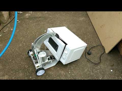
    The drive motor assembly then attaches to the chassis with the same holed and threaded box section the holds the rest of it together, so it was back to drilling and tapping. Here it is bolted on, however at this point I found the first main mistake that I have made. The holes for the upper fixing were off by a few mm, so I had to elongate them to make it fit. I’m not really happy with this so I’ll have to take a look at the CAD to see if I can figure out where I went wrong and then get another one cut.
    picture 2.jpg picture 3.jpg

    Next up, the base plate. I have only had time to get one fixing in it so far but it gives you an idea of how it’s going to look. The design is slightly asymmetrical, but it saves a few grams of weight, so be it. Once this is on and properly fixed, I’ll look to getting all the electrics fitted.
    picture 4.jpg

    On a final note, I have seen videos of people using taps in a battery drill to thread holes. This would speed things up for me a bit, so I was wondering, can I just put my normal tap in the drill and use it that way? Or if I do that am I likely to break something and do I need a special tap for doing it that way?
    Last edited by Al_; 13 March 2017, 11:52.

    Comment


    • #32
      As far as I know, people usually use spiral taps for drill-tapping, I think it's because the flutes help remove the material. However I resorted to my drill with a normal hand-tap in the chuck to tap the holes for Aegis' scoop, and that was in 6082 Aluminium. As long as you keep giving it a little half-turn backwards every few revolutions, you should be ok from my experience. Just make sure you keep clearing the shavings.

      Comment


      • #33
        I quite like using WURTH taps, because they come with 3 tapers, allows you to build a thread in harder metals.

        Spiral should be fine for plastics and light alloys. Just keep the speed down.

        Comment


        • #34
          Best thing to do is put it on the highest speed possible, on hammer setting and push as hard as you can..... hahaha just kidding..
          whenever I thread metal I always put the tap in my drill... very slowly though.. and definitely not on hammer haha. was tapping 10mm steel the other day with a 6mm thread just fine. Only time I have snapped one like that is when my battery ran out and I replaced it with fully charged one and wasn't expecting the speed increase so much...... snap! I would have thought you would be fine in alu.

          Comment


          • #35
            Thanks for the advice everyone, I'll give it a go with what I've got, take it steady and see how I get on.

            Comment


            • #36
              I love how your robot's looking Al. What hydraulic pump are you using, and where did you get it?

              Comment


              • #37
                Thanks Andy. The pump assembly comes from Interfluid, at http://interfluid.co.uk I think hydra products also sell them www.hydraproducts.co.uk and I have seen them pop up on amazon occasionally too.

                Comment


                • #38
                  It’s time for an update that leaves the robot looking largely the same as it did before, but with lots of little bits changed internally that are hard to see.

                  Continuing from last time, I have finished mounting the baseplate to the chassis. I followed the advice and tapped the holes for the fixings with the battery drill, much quicker and the tap is still in one piece, so many thanks there. After that, it all came back to bits for re-assembly, but this time with the hydraulics back in. I took the opportunity to remove a couple of sharp edges I had found on the chassis sides, and also to add a smear of grease everywhere I have moving metal on metal contact

                  I found the back plate was little harder to fit this time, the reason being the force the arm puts on the chassis when it is all bolted together. I had left room in this area for some support bars, so I made one from some aluminium tube and that brought it back into line. I have also made some wheels and fitted them to the drill gearboxes. They are not the final wheels as these are too heavy, but they are the correct size so I can at lease see how the robot is sitting. At this point I was able to sneak the robot in to work for a check on the weight. We have some scales we use for weighing things we are sending out and they are the most accurate I have access to. It came out about 250g up on what I have calculated for what was assembled so for. Not a disaster and I have a couple of places I can shave some weight off if need be.

                  Next job was to make a start on the electronics. Both drive ESCs sit between the chassis sides and under the ram, so hopefully will be fairly well protected there. Likewise the weapon ESC sits under the steel valve block for the weapon. The weedy wires that the drill motors come with were replaced with some 12AWG silicone insulated wire and bullet connectors added. Everything electronic has remained fairly compact but it has been at the expense of ease for running wires and connecting up cables. Battery placement has been sorted and the battery connector and removable link have been made too. That was as far as I could take things as I’m waiting on the fuse, power LED and a case for the RX to be delivered which I should have before the end of the week. Here it is as it currently looks:

                  picture 10.jpgpicture 11.jpg

                  After I have the parts and the electronics are finished I should be able to power it all up together on the bench for the first time. This will also give me chance to try and get the mixing for the drive working on the TX.

                  Before I can stick it on the floor and drive it around I have to sort out the front wedge. I have given myself 2 ways that I can run it, but I could do with a bit of advice on the arena floors having never seen one. My first option is to take the front of the wedge down almost to a ‘blade’ and let it contact the floor and take the weight of the front part of the robot. This would get it the lowest but if I do this am I likely to keep hitting the edges of the floor panels and suffer from it as a result? My second option is a pair of skids behind the front wedge. These would instead take the weight and hold the edge of the wedge just a hair or so off the floor and with the shape of them I should be able to ride over the joins and unevenness (if there is any!?) of adjacent floor panels. Would this be a better solution from people’s experience of being in the arena? Thanks again for any advice you can offer

                  Comment


                  • #39
                    Most robots do fine with just scraping the front wedge along the floor directly, there is a few uneven parts normally but they seem to run over them fine. Fantastic looking robot by the way!

                    Comment


                    • #40
                      Robot is fit as.

                      I build a lot of 2wd pushers and grind the blades to a point each match. Put your front wedge scraping the ground with weight on it to get under opponents and leave clearance at the back of the robot. A quick back/fwd jiggle on the drive stick will give the front the mm or so it needs to ride up if you get stuck. Failing that you can reverse off a damaged arena tile and fight elsewhere that the floor is undamaged.

                      Most robots literally run planing the surface off the arena floor.

                      It is a myth that you need to pick someone up to push them. You just need to shunt them up a couple of mm to take the weight from their drive wheels and you can then push them around till your hearts content.

                      Comment


                      • #41
                        So progress on Pressure Point has been slower then I would have liked over the last couple of weeks, but here is what has been going on.

                        I have virtually finished the electronics now. The fuse has been installed, the Rx has been put in a case and installed, and the connectors for the power LED are done. I have another link to make, (the current one uses Black wire, and I want one that uses Red), but otherwise I hope that's it for electronics. The final wheels have been done, and I have followed the tried and tested method of nylon wheels with bike tires cut down and screwed to the outside of them. These are much lighter than the original wheels I had on it that you can see in the old updates.

                        pic 1.jpgpic 2.jpg

                        In the pictures above you can see that the 2 self-righting arms are on the robot, but not yet connected up to anything to make them work. There is also a new piece of armour to protect the hydraulic tank from the back. The self righting arms should flip the robot back over if/when it end ends up on its side. It wont balance either on its front or on it top. And if it gets knocked onto its back it is designed to drive around in this state and can be righted by either a sharp switch in direction (theoretically) or by extending the ram.

                        The next part of my plan was to give it the first test of driving around under its own power. Over Easter I took it over to the families house as they have a bit of smooth concrete I can drive around on which is something I don't have. Straight away there was an issue with the drive motor mounts which meant I couldn't drive it around. The front mount is a bit loose, not by a lot, but enough to stop it driving. Its frustrating, but better than turning up to an event like that I suppose. But the day was not a waste, as there was an old microwave the crusher could have a play with:

                        pic 3.jpgpic 4.jpg

                        I'll stick the video up in a couple of days when I get chance.

                        I was hoping to make the Manchester event next weekend, but I think I have at least a couple of days of work left including re-making the front motor mounts, making the armour, connecting up the self-righters and giving it a test. Again its frustrating as the event it not too far away, but I'll look to the next one.

                        Comment


                        • #42
                          Holy accordions, Batman, that's one folded microwave! Glad to see things are shaping up to some degree. I sure as heck do NOT want to get caught on the end of that crusher arm. Great work so far!

                          Comment


                          • #43
                            No more microwave cooking for that one.

                            Comment


                            • #44
                              Quick video clip as promised:

                              Comment


                              • #45
                                That's like a kick to me when I'm already down as I just can't find time to make progress hahahah ... that's really brilliant progress though mate..
                                Especially seen as we both started this at the same time and all I have is a 4wd rambot made out of ply and a weapon test platform..
                                I went the mechanical route rather than hydraulic and hitting no end of problems. Latest one is gears losing teeth like a 90 yr old bloke. Lol.
                                its been great to follow your build though, can't wait to see it in action and test against something tougher.
                                :-) :-)

                                Comment

                                Working...