Announcement

Collapse
No announcement yet.

[FW] Wedge Spinner in time for Robo Challenge champs!

Collapse
X
 
  • Filter
  • Time
  • Show
Clear All
new posts

  • #31
    At the moment I have a small 3AH 5S pack and a 3.3AH 6S pack, for drive and weapon separately powered. This is mainly because I didn't think I could run the 18V motors at 22V without doing something bad to them. For now, I'll probably stick with what I have and 3D print a fuse block that holds two fuses into a single removable link for both, but thanks for letting me know the logic behind the fuse amp choices.

    That pulley quote came from protolabs.co.uk :P I think I will avoid them for.....ever...

    Comment


    • #32
      If you want to use XT90 connectors, I can send you the STL file for this dual link base:


      Its been working well for the last two years and will save you some valuable time.

      Comment


      • #33
        That would be a huge help, it's exactly how I was thinking of doing it in my head, although yours looks nicely machined from HDPE while mine will be an ugly lump of printed nylon

        Comment


        • #34
          Nah, that part was printed in nylon by Shapeways before I had my own printer and then painted. I have printed similar parts at home and they are really tough with a 100% in-fill. I will send you a PM with the file download location. BTW, here are three good reasons why its better to have two separate fuse links rather than one double:

          * Safer to test the drive motors by themselves.

          * If one fuse blows, you are not throwing out a working fuse as well.

          * Its quite hard to pull out two XT-90 connectors if you need to in a hurry.

          Been there, done that

          Comment


          • #35
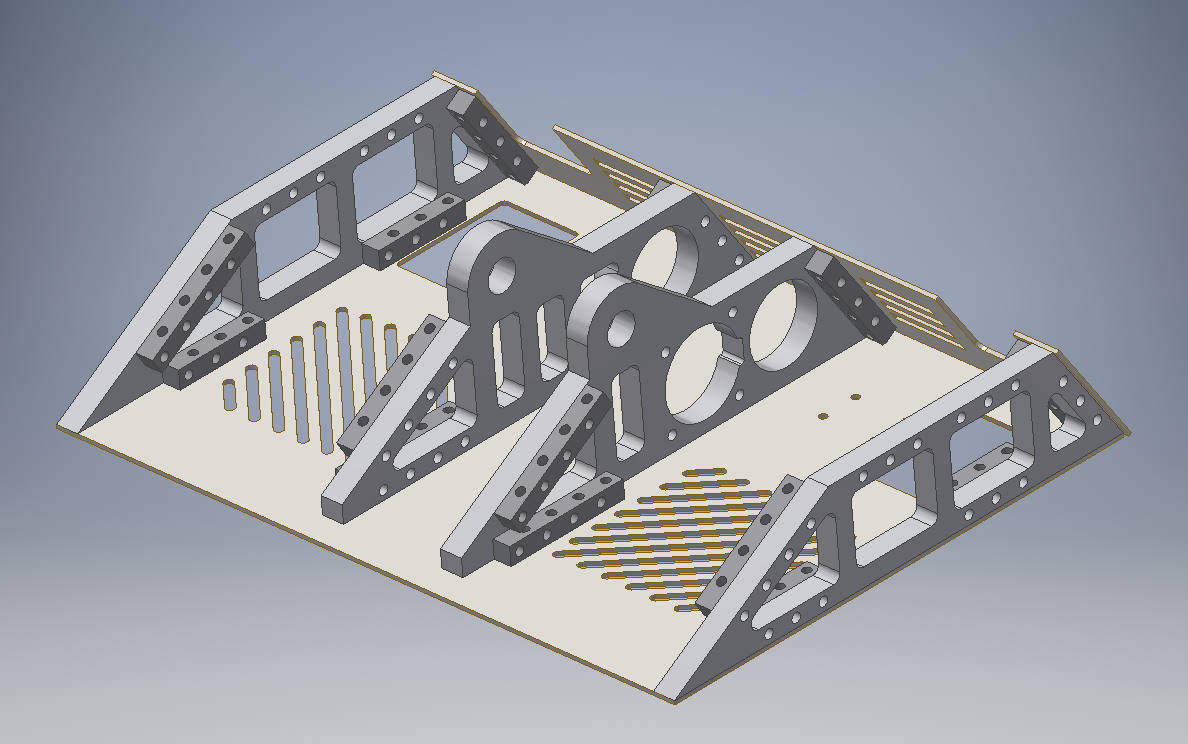
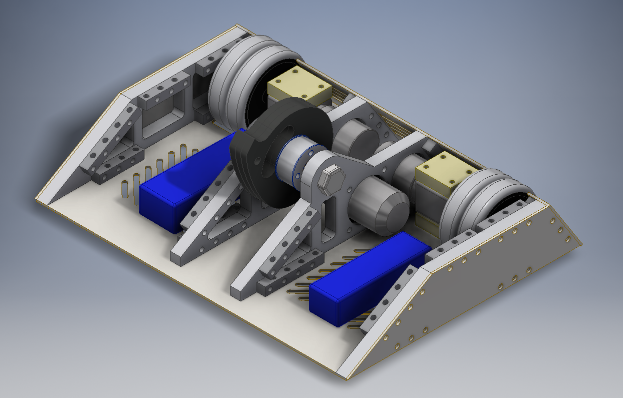
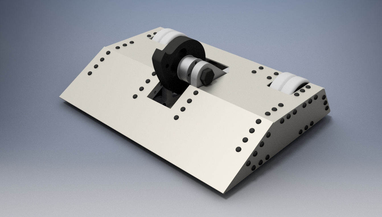
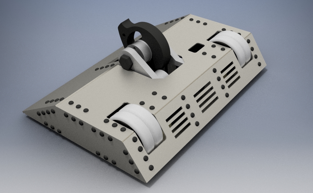
            Ok, I think the CAD model is finally finished! The only thing I'm not sure about is the placement of the removable link access hole on the top plate, looks very axe-able, but im not sure where else to put it tbh.

            According to Inventor, it current weights 11.5kg, with only the wiring/small electronics, fuse box, belt and a bunch of shock-absorbing things missing. So I should end up comfortably under the weight limit providing nothing is too inaccurate. If this is the case then I'll probably add some fat cuts of HDPE to the sides as extra armour.
            It's basically threaded bars on wheels:


            Comment


            • #36
              Looking good! Is there any particular reason for the slots in the back panel? They are taking a lot of strength out of the armour in that area and other vertical spinners will rip them up. The weapon axle looks like it might be a 20mm bolt - that's not really ideal for running a bronze bearing as the bearings need a highly polished surface with accurate dimensions or they wear out fast. Other than that, it looks like a winner

              Comment


              • #37
                Originally I was very tight for weight, so they were there for weight reduction, but then I discovered inventor thought my motors were solid steel and 2kg each... haha. I guess they serve no purpose now, I could get rid of them. The weapon axle is indeed an m20 bolt made of 10.9 steel. It seemed like the easiest option for me. How fast would the bronze bearings wear down on that do you think? If its a matter of replacing them every few matches, then that's fine with me. I can revisit it when I have more time to spare perhaps :P

                Comment


                • #38
                  Given the short build time you have, an M20 bolt makes sense. Bronze bearings are meant to run on precision ground & polished rods but they will run on anything vaguely round with a shorter lifespan. As long as you have some spares and oil the bearings regularly, they should last long enough. If possible, wait until you have the bearings before buying the bolt; take the bearing along and check to see how it fits on the bolt and how smooth the bolt's surface is. I use bronze bearings running on M8 bolts for a lower speed application and they work very well after I polished the bolts a bit.

                  Comment


                  • #39
                    Originally posted by Giles View Post
                    The only thing I'm not sure about is the placement of the removable link access hole on the top plate, looks very axe-able, but im not sure where else to put it tbh.
                    Most people put a cover over the access hole; it seems to be allowed in the rules as long as no tools are needed to open it.

                    Comment


                    • #40
                      Originally posted by Giles View Post
                      The only thing I'm not sure about is the placement of the removable link access hole on the top plate, looks very axe-able, but im not sure where else to put it tbh.
                      As per the rules it must be a way from any moving parts (wheels tend to be ok so long as its not sharing the same hole or anything stupid) and it must be accessible without tools. Our robots have the rather prominently on the side and top, others bury them under panels inside the robot, these panels can swing shut, be held on with velcro or pinned down with a wing nut. TBH, Link placement is one the things that annoys me the most and tends to be the last thing on my mind when designing a robot, hence Conker 3 and Binky's exposed link positions.

                      Looking B-E-A-Utiful btw!

                      Comment


                      • #41
                        Since you have the weight you could either look at slopped sides or adding a layer of HDPE on them, horizontals will love to have a go at those and verts with a good run could take a nice chunk and possibly bend the chassis. My spinner has flat sides so I went for layering it up with HDPE and it should do the job

                        Comment


                        • #42
                          My thoughts exactly! I can put 15mm HDPE on the sides with counter sunk holes to cover the bolt heads too. This will stop verticals catching the bolts and protect from horizontals!

                          I might not be using a bolt for a weapon shaft any more, as Harry has offered to machine me one along with the pulley. Just need to clear things with him I have the bolts as a backup just in case though.

                          Comment


                          • #43
                            Ordering the armour and frame work this week. How does this sound compared to what other bots have? I've no idea if I've gone too heavy or gone too light on the protection haha.

                            Frame: 15mm alu 7075 frames
                            Base/top/back/sides: 2.5mm grade 5 titanium
                            Side extra: A layer of 15mm HDPE (optional/replaceable)
                            Front Wedge: 5mm grade 5 titanium
                            Weapon: 3 stacks of 8mm hardox discs, with a spare in case 3 just isn't enough :P

                            Comment


                            • #44
                              That sounds pretty good - is there any spare weight to increase the titanium on the back? With no HDPE, its the weak point in the armour.

                              Comment


                              • #45
                                I should have just about 1.5kg to spare I think. Not sure how much the HDPE sides will weigh, but probably enough to have atleast a 5mm or 10mm sheet on the back

                                Comment

                                Working...
                                X