Announcement

Collapse
No announcement yet.

Skipdiving Robotics

Collapse
X
 
  • Filter
  • Time
  • Show
Clear All
new posts

  • #46
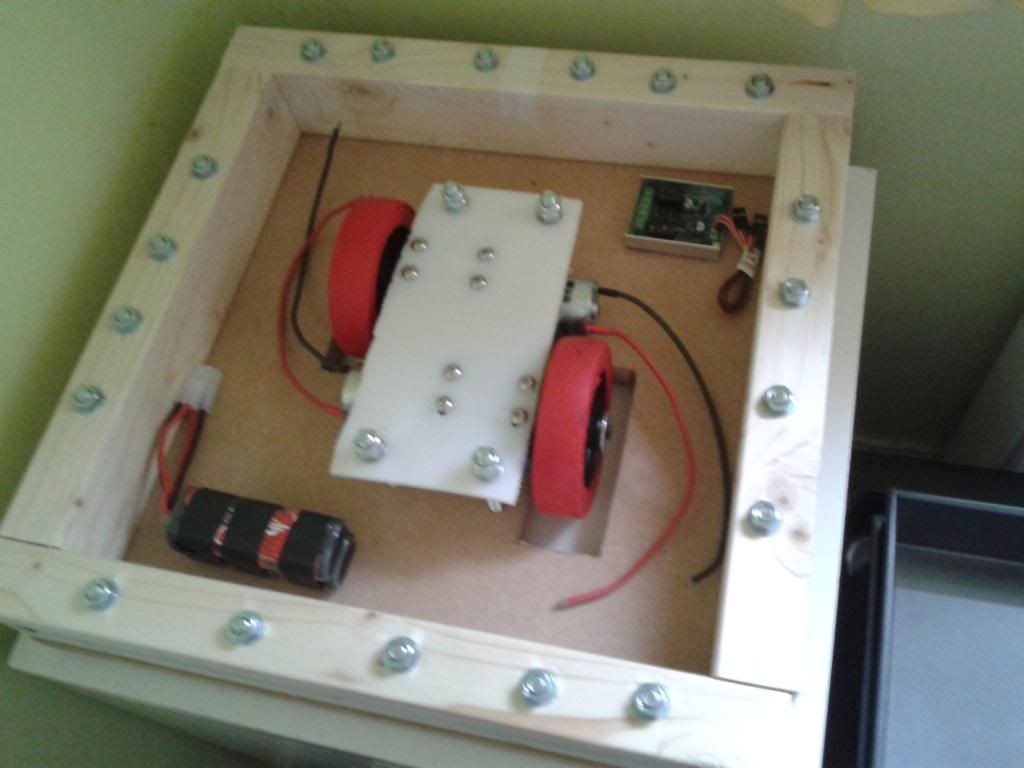
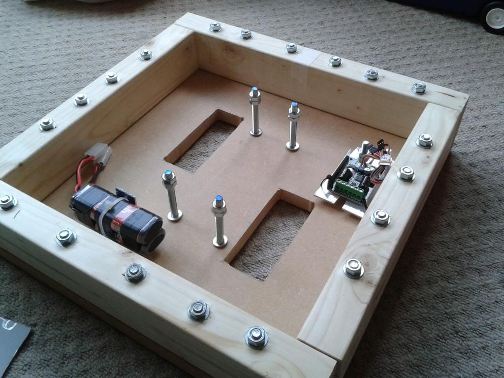
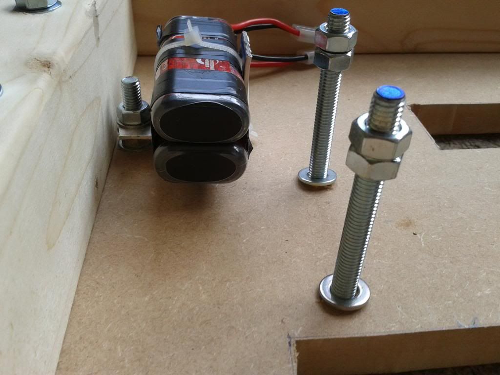
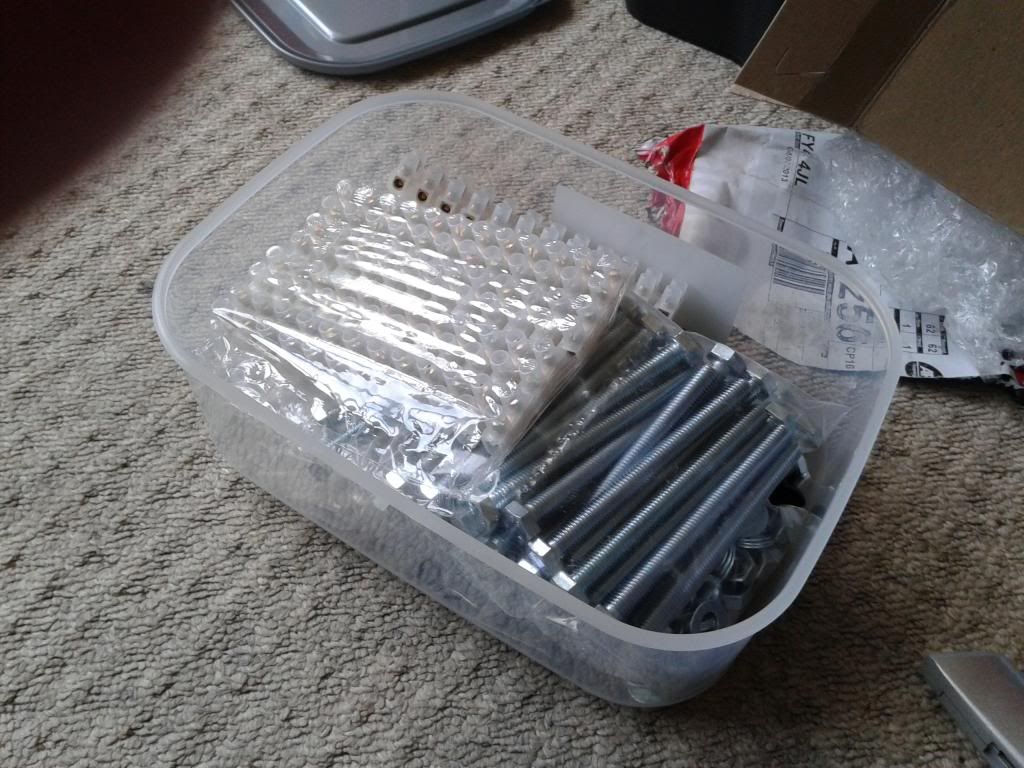
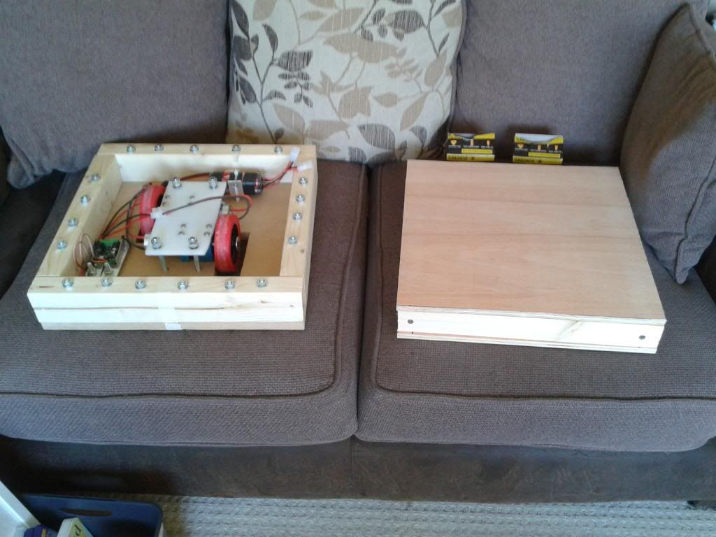
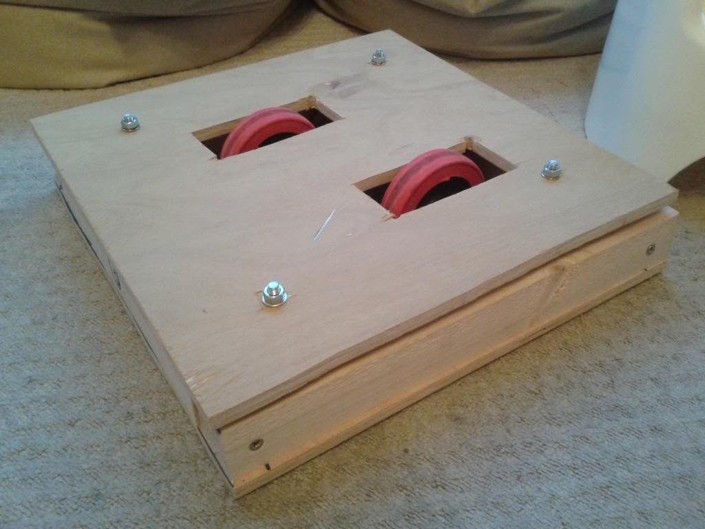
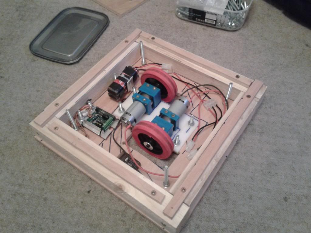
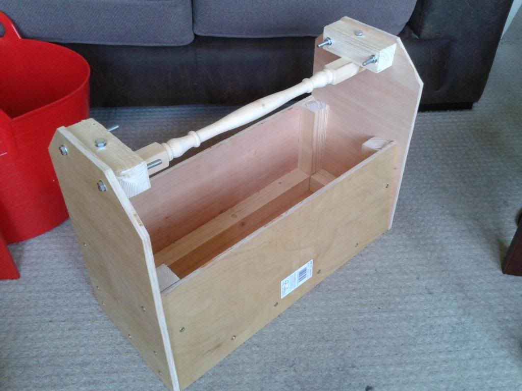
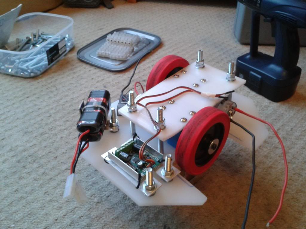
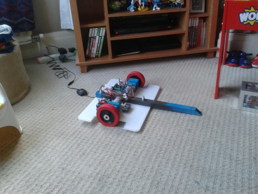
    Some more pictures, I have some brackets that I've made but I've yet to pull it all together and get pictures of it all together. I'm basically waiting for another pack of the main bolts to turn up. It holds it all together but they'll be another fortnight or so.


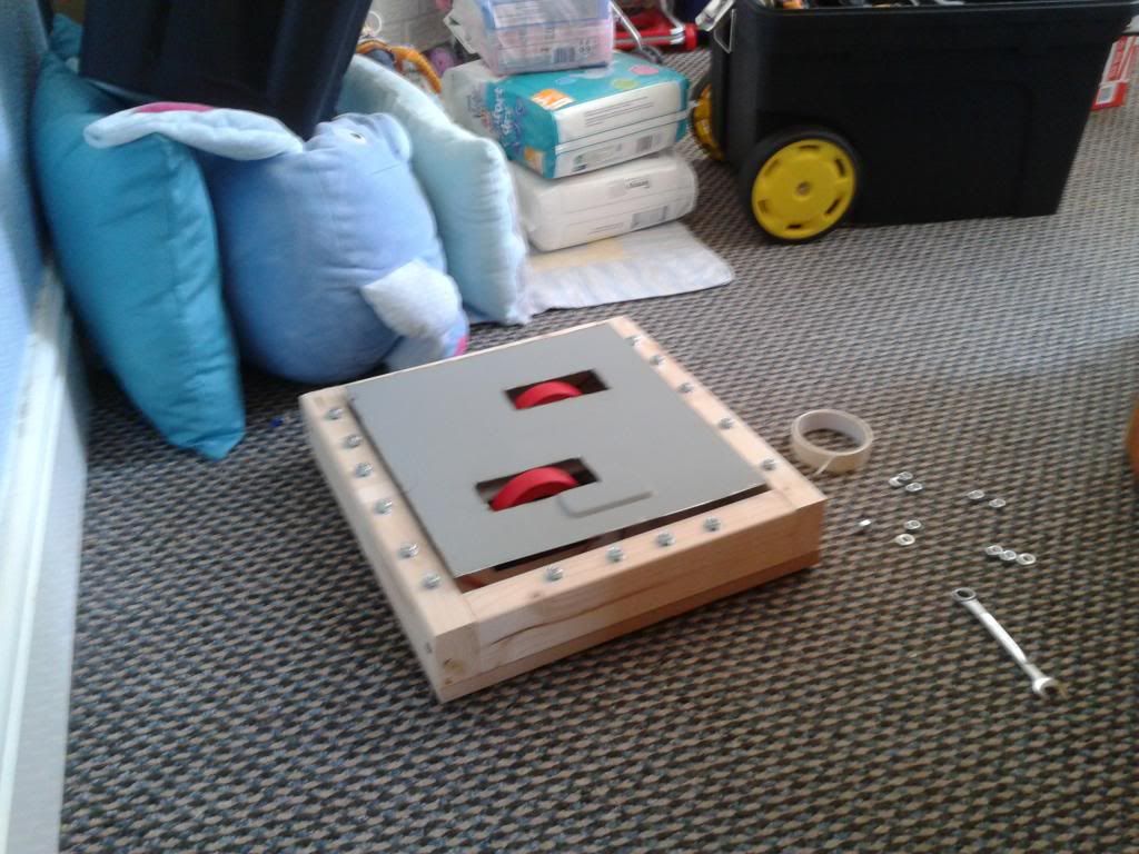
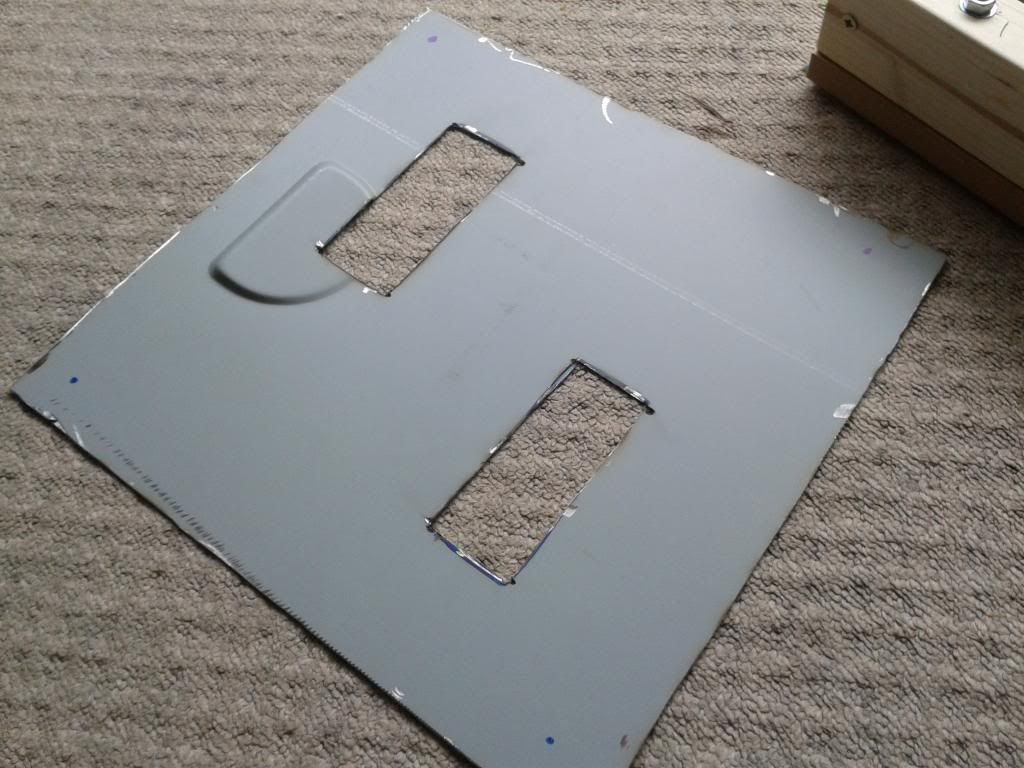
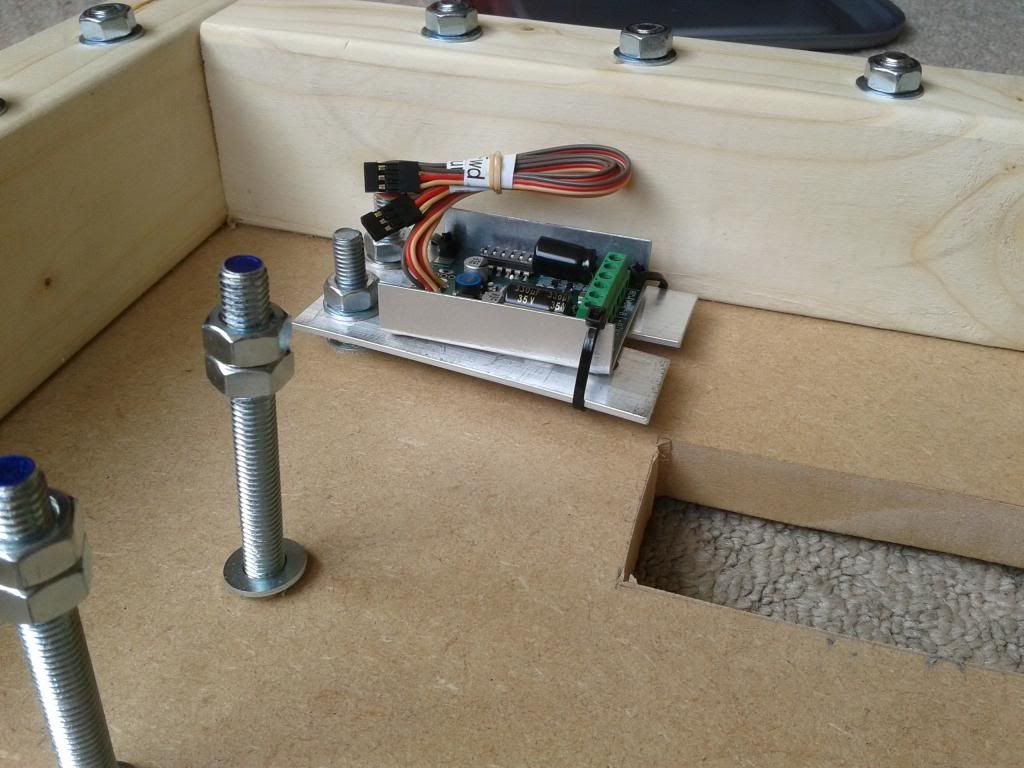
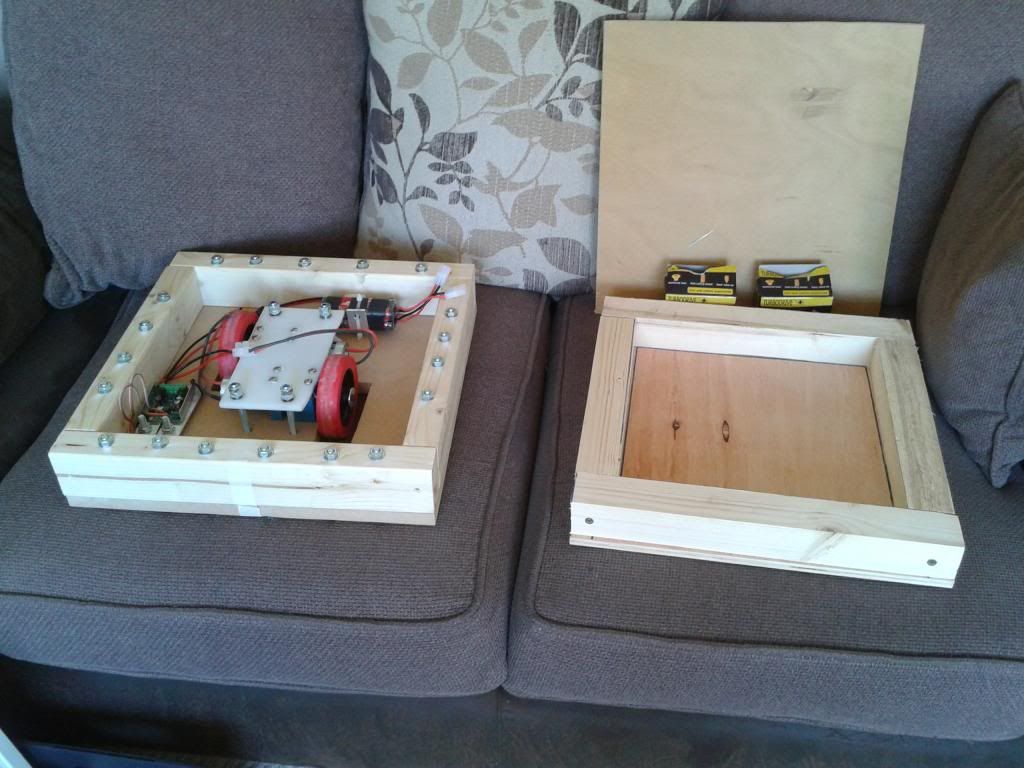
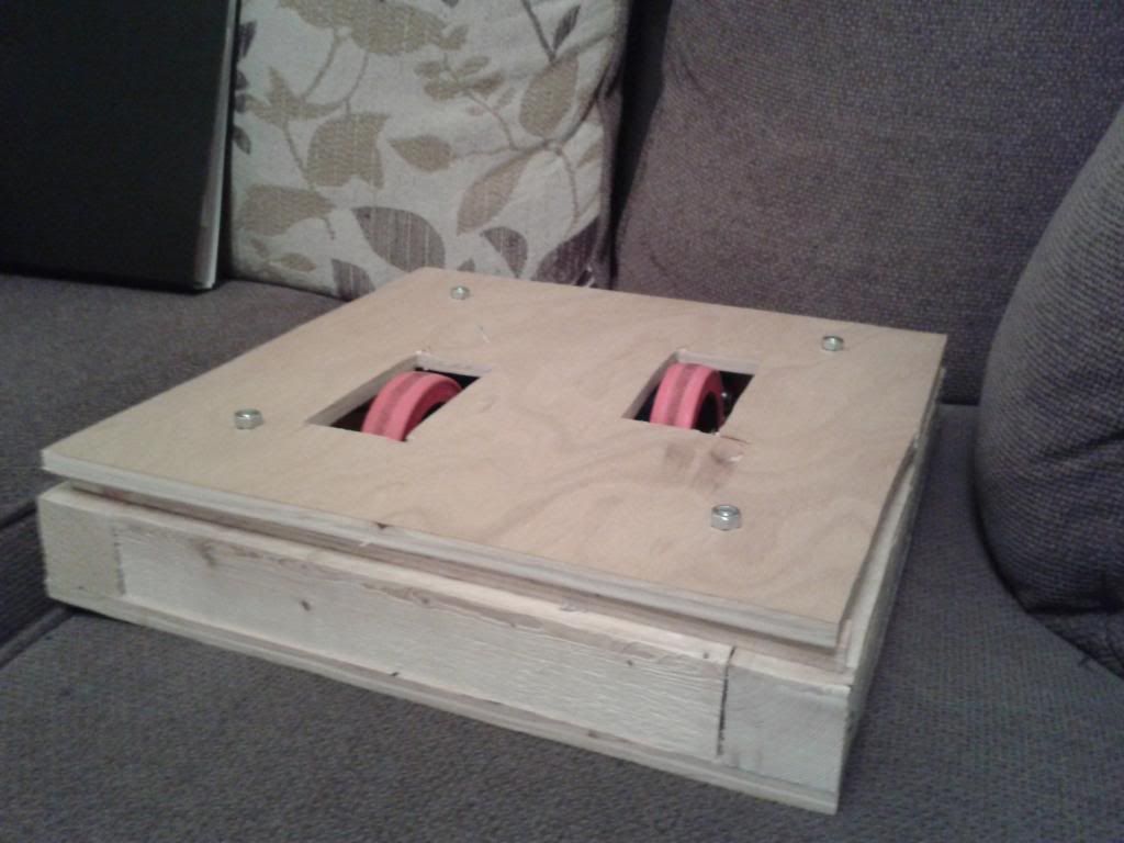
    Just thought I would say the top panel isn't sat square in the second picture! When it's on properly it sits square and flush covering the whole top! Thinking about calling it Wabbajack after my favourite Skyrim weapon lol.
    Last edited by daveimi; 26 May 2013, 14:18.

    Comment


    • #47
      I'm not quite sure why, but I can see those rubbery corner-protectors for keeping kids safe from tables etc on each corner to cushion it lol

      Comment


      • #48
        That's a really good idea lol. I like the way you're on the same wacky out the box wavelength lol.

        Comment


        • #49
          I have a bit more to add about Wabbajack.

          Items started to get bolted down (drive pod removed for access)


          The lid marked and ready to drill.


          This has a bit of the home-brew shock mounts I've been trying.


          And again with the speed controller lol.


          And the big box of fresh bolts that arrived so I can carry on cutting and drilling the lid.


          Next plans over the next few days are to start looking at making the removable link and some sort of bracketry for that. This also sort of ties in with wanting to start wiring at the weekend as well. I do a lot of wiring etc with work so imagine the cabling will come on quite quick once I get started. It'd be nice to have it running by the middle of the summer. I also need to order a Tx/Rx at some point as well.

          I also have plans for an ant and a heavy version of Wabbajack, will see how this goes first! Any thoughts/questions/oppinions welcome to liven up the thread!!

          Comment


          • #50
            It's running! Don't have a great name for it yet (answers on a post card lol). I've tried it up and down the drive and taken a layer off the laminate and it works great!

            Obviously the old girl needs the lid bolting down and a rewire but the basics are there. It's really fast!

            CLICK ON PICTURE FOR VIDEO


            Sorry for the naff video it's really hard driving and video-ing at the same time!
            Last edited by daveimi; 16 June 2013, 21:16.

            Comment


            • #51
              Originally posted by daveimi View Post
              Don't have a great name for it yet (answers on a post card lol)
              To post the postcard, I'd need a stamp. Why not put a picture of the Queen's head on the top panel and call it Giant Postage Stamp (GPS for short ). The proportions seem about right for it.

              And looks like it drives quite nicely too. With wheels that close together, the robot can have a tendency to veer off when trying to drive in a straight line, but it looks pretty controllable in that video.

              Comment


              • #52
                Squared
                or a small 2 on the top right corner of the robot

                Comment


                • #53
                  These are awesome ideas!

                  It drives really nice, I was really surprised by how smooth it is and everything.

                  Comment


                  • #54
                    I'm gonna have a good go with it tonight and I'm worried about the straight line side of it lol.

                    Comment


                    • #55
                      I was really into driving the robot round last weekend, but a few things came up. The bolts caught on the floor and the ground clearance wasn't the best. I messed about till mid-week trying to tidy bolts and stuff up before I decided to start on a fresh body shell. Same design, just screwed and cleaned up. I've nearly finished the body and I'm in the process of transferring everything over.

                      It's a lot more in proportion and I've done away with the MDF. I now have 12mm marine ply for the top and bottom and 2x2 for the sides. The gap between the body and lid is deliberate, I plan to have LED strips all the way round the gap to look snazzy lol. There's a 10mm spacer that will sit round the top of the body allowing for the link holder and LED strips.


                      The lid needs tidying up as it's a tiny bit too big and stuff but I was excited to get it together to see how it looked.

                      Comment


                      • #56
                        Bit of a naff update compared to the other robots on here.

                        Made random trim and started wiring properly. Also had a go at making a random toolbox (needs a better handle and straightening out).


                        Comment


                        • #57
                          Had the brain wave today of doing away with the naff lid and building a big lifting arm for the top instead. I could power it with a juicy linear actuator from Mr Gimson.

                          Comment


                          • #58
                            The CAD department knocked this up for me to bung on here.

                            A grabber and a lifter. It'll be as shonky as the rest of the robot I'm pleased to announce.


                            Comment


                            • #59
                              Thought I would bring this up to date. I've built the running gear onto a plate that can be moved as a "module" from shell to shell. This obviously works for me as I have little fabrication skills other than keeping battered cars on the road and building street luges for my 4 year old. Therefore, I'm largely aware that my robot is like a hermit crab, constantly looking for the next shell in which to stow it's behind. To this end, we (I say we, I mean me, my crazed father and a 4 yr old) decided the best thing to do would be to screw everything to a bit of plastic. Then, which ever shell presents itself we can bolt said plastic into and away we go. All this method requires is steady supply of scrap and rubbish (of which there is plenty in Blackpool).

                              So please see below picture of our new "module". This can be bolted into any given shell and will quite happily run round the house on its own. The wooden shell pictured above broke up after a weekend of fighting a Tamiya Fighter Buggy. I don't have a picture as of yet of the new metal shell, however it's based on a money tin 30x30cm and about 2 inches deep. The below module bolts in nicely provided you cut a pair of wheel slots and bolt holes. This week I will finish it's new body off and slap up a picture. I'm trying to enquire as to how I get us to the Doncaster Dome event in September?? which would appear to be a non spinner event.

                              All comments and slagging off's welcome / encouraged

                              Dave, Skipdiving Robotics.


                              Last edited by daveimi; 4 August 2013, 21:40.

                              Comment


                              • #60
                                Ok! After months and months of trial and error, we have our design that we're going to stick with for a couple of years! There is a body shell being made from Ally/Steel at the minute, and also a new base plate being made as this is a chopping board. But at least you get the idea. Meet Rag N Bone.


                                Comment

                                Working...
                                X